Why Does Industrial Gearbox Reducer Mounting Matter?
An industrial gearbox reducer is normally selected as part of a complete drive system rather than as an isolated component. The reduction ratio determines output speed, but mounting position, motor compatibility, shaft configuration, and load requirements also affect whether the reducer fits the machine properly. These details become especially important when a gearbox needs to be integrated into an existing conveyor, mixer, packaging machine, or other powered system.
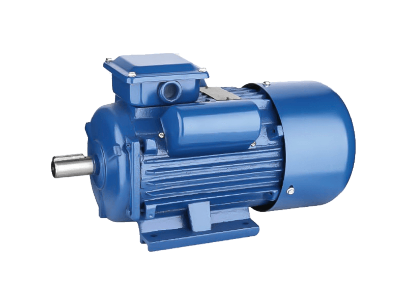
A gearbox reducer changes the speed and torque relationship between a motor and the equipment it drives. In many industrial applications, the motor operates faster than the driven mechanism requires, so a reduction gearbox is placed between them. The choice of ratio determines the approximate output speed, but the physical arrangement of the drive system also needs to be considered from the beginning.


Mounting orientation is one of those details that can easily be overlooked. Depending on the reducer design, the unit may be installed horizontally, vertically, or in another defined position. This is not simply about whether the housing physically fits. The internal lubrication arrangement can also depend on the installation orientation. When specifying an industrial gearbox reducer, the intended mounting position should therefore be checked alongside the ratio and output configuration.
Worm gear reducers are commonly used where compact dimensions and substantial speed reduction are required. Inside the housing, a worm shaft engages with a worm wheel, creating a sliding contact between the two components. Material selection for the gear pair is consequently important. A hardened steel worm combined with a bronze worm wheel is a common arrangement, with lubrication helping control friction and heat during operation.
Motor compatibility is another practical consideration. An industrial gearbox reducer may be paired with motors of different frame sizes and power ratings, but the mounting interface needs to correspond. Flange dimensions, shaft diameter, center height, and adapter requirements can determine whether the motor and reducer can be assembled directly or require an additional component. Checking these dimensions before ordering can prevent unnecessary changes to the machine frame.
Output-shaft configuration also depends on the driven equipment. A solid shaft may be appropriate where the reducer connects to a coupling or other transmission component, while a hollow shaft can simplify certain direct mounting arrangements. The required output speed and torque should be considered together with the shaft arrangement because a suitable ratio alone does not guarantee that the reducer matches the mechanical load.
These reducers can appear in conveyors, mixers, packaging equipment, material-handling machinery, and other production systems. The operating environment can influence housing requirements, lubrication intervals, and protection considerations. Equipment that runs continuously under significant load may also require a different reducer size from a machine with intermittent operation, even when both systems need a similar output speed.
For equipment manufacturers, a practical specification review should therefore include reduction ratio, motor frame compatibility, mounting orientation, input and output shaft dimensions, rated torque, operating duty, and available installation accessories. Looking at these factors together makes it easier to determine whether an industrial gearbox reducer can be integrated into the intended machine without changing the surrounding drive structure.
What's Your Reaction?