Why Does PCB Connector Plating Thickness Matter?
A connector may work normally during initial assembly yet develop unstable electrical contact after repeated mating and environmental exposure. For a PCB Connector, contact plating, base metal, solder-tail alignment, retention force, and housing precision all contribute to long-term performance. Looking at these details together gives engineers and procurement teams a clearer picture of how connector construction relates to actual service life.
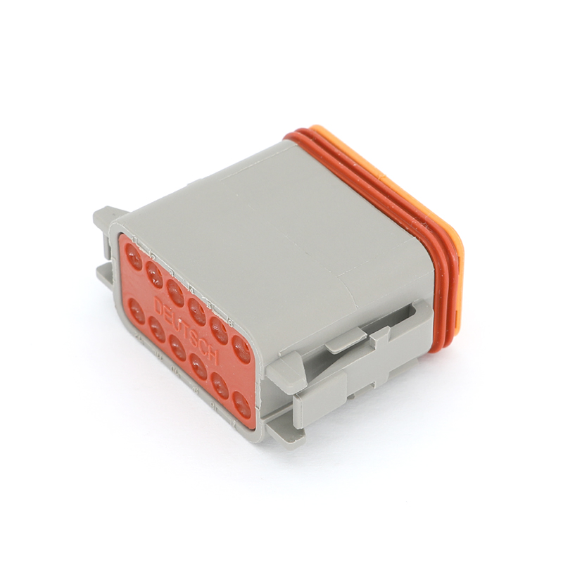
A PCB Connector can experience very different working conditions depending on how often it is connected and disconnected. A connector used once during final assembly has different requirements from one that technicians may open repeatedly for inspection or maintenance. This difference becomes particularly important when selecting the plating applied to the contact surface.


Gold is commonly used because it offers good resistance to oxidation and maintains a stable contact surface. However, the thickness of the gold layer matters. A thin gold flash can be suitable for applications with limited mating cycles, while connectors intended for frequent disconnection generally require a heavier plating specification. Repeated insertion creates mechanical friction between mating contacts, gradually wearing the surface layer. If the plating is not matched to the expected cycle count, the underlying material can become exposed earlier than intended.
The material beneath the plating also affects contact behavior. Nickel underplating is commonly used as a barrier between the surface finish and the base alloy. Phosphor bronze and beryllium copper are frequently selected for contact springs because they provide a combination of conductivity, strength, and elastic recovery. Beryllium copper can retain spring characteristics effectively under repeated movement, while material selection must also take manufacturing requirements and cost into account.
For surface-mount versions, solder-tail coplanarity introduces another important consideration. When connector terminals do not sit within the required plane, some contacts may not form consistent solder joints during reflow. Stamping accuracy establishes the basic terminal geometry, but transportation and tape-and-reel handling can also introduce small deviations. This is why dimensional inspection is relevant before components reach the assembly line.
Mechanical testing provides another way to evaluate a PCB Connector. In applications involving repeated mating, insertion and withdrawal force can be measured throughout the rated cycle life. Contact resistance can also be monitored before and after cyclic testing to identify gradual changes that would not be visible during a simple visual inspection. Housing latch retention and plating adhesion may also be evaluated when vibration or thermal cycling forms part of the application environment.
Housing precision matters as well. Connector pitch depends on the accuracy of the injection-molded housing, and gradual cavity wear can affect dimensional consistency during long production runs. This becomes increasingly important with fine-pitch designs, where even small deviations can influence mating alignment.
For a PCB Connector, long-term reliability therefore comes from several controlled details working together. Plating thickness, contact alloy, terminal geometry, retention characteristics, and mold precision all contribute to how the connector behaves after repeated assembly and actual service conditions.
What's Your Reaction?